S-AES17 Low Pass Filter
S-AES17 is a hardware filtering kit for optional installation in System Two, System Two Cascade or Cascade Plus that satisfies the AES17-1998 specification for a standard low-pass filter for THD+N measurements of digital-to-analog converters (DACs) which exhibit high-level out-of-band noise. APWIN 2.20 and later versions support the use of this filter. The filter can be set to either of two bandwidth selections: 20kHz or 40kHz. The S-AES17 Low-Pass Filter Option improves upon the capabilities of the earlier S2-AES17LP filter, which is no longer available.
S-AES17 SPECIFICATIONS

Passband Response 20 kHz setting:

±0.10 dB,10 Hz–20.0 kHz

Passband Response 40 kHz setting:

±0.10 dB, 10 Hz–40.0 kHz

Stopband Attenuation 20 kHz setting:

>60 dB, 24.0 kHz–200 kHz

Stopband Attenuation 40 kHz setting:

>60 dB, 48.0 kHz–200 kHz

Residual THD+N (1 kHz) 20 kHz AES mode:


System Two and System Two Cascade

<(0.0004 % [–108 dB] +1.0 µV)

Cascade Plus

<(0.0003 % [–110.5 dB] +1.0 µV)

Residual THD+N (1 kHz) 40 kHz AES mode:


System Two and System Two Cascade

<(0.0005 % [–106 dB] +1.4 µV)

Cascade Plus

<(0.0004 % [–108 dB] +1.4 µV)

 
The figures below show the curve of the Audio Precision AES17 Low-Pass filter in the 20kHz mode. The orange lines indicate the AES17-1998 specification. For further information, refer to the AES17 Filter Description, Installation, and User's Guide.
Response curves of the S-AES17LP Low Pass Filter for System Two. The blue curve is the typical filter response, the orange line is the AES17 specification.
Filter stop band attenuation.
Filter pass band response (ripple).

Background
Digital-to-analog converters frequently use delta-sigma modulation and oversampling techniques to achieve high performance at an affordable cost. The noise inherent in this type of conversion is pushed up in frequency out of the audio band by means of high-order noise shaping. The resultant signal is quiet within the audio range but carries large amounts of out-of-band noise.

Measuring the audio performance of such converters can be a challenge for most contemporary wide-band audio distortion and noise analyzers. These instruments are designed to characterize classic analog audio devices, which typically exhibit a noise floor spread evenly over the full spectrum of the analyzer, usually diminishing with increased frequency, due to bandwidth limitations above the audio spectrum. Out-of-band noise and interference are expected to be low in amplitude in relation to the signal, so band-limiting or noise-weighting filters, if needed, are inserted at the end of the measurement path, following several gain stages. When measuring classic analog audio devices, this approach yields accurate and repeatable THD+N results.

The spectrum of the noise floor of a noise-shaped delta-sigma D-to-A converter, however, shows a steeply rising energy characteristic beyond the 20 kHz upper limit of the audio band. When measuring low-level signals, the energy contribution of this ultrasonic noise can be substantial. In many situations it can overload instrument gain stages or throw off ranging circuits and cause grossly inaccurate measurements. Conventional band-limiting and noise-weighting filters cannot solve the problem because they are located too late in the measurement chain—the damage has already been done.

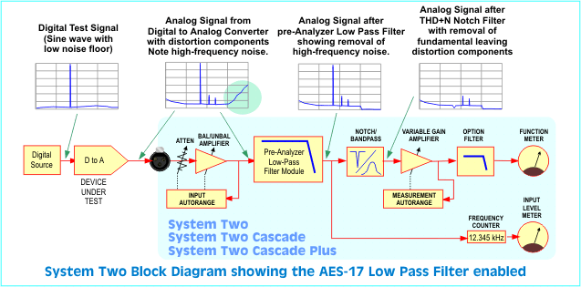
The Audio Engineering Society has defined the techniques for measuring digital audio equipment—that is, systems that contain digital to analog converters. AES17-1998 specifies the use of a "Standard low-pass filter" (section 4.2.1) that has a sharp roll off above the audio upper band, 20 kHz. The filter is specified to have a stop band attenuation of 60 dB or better above 24kHz, an aggressive slope. The filter must be inserted early in the measurement path in order to remove the out-of-band noise before the measurement notch filter and its subsequent gain. This will insure that the "+N" part of THD+N contains only the in-band noise and distortion. Without the filter, the automatic gain ranging that normally follows the THD+N notch filter can behave incorrectly and the resulting measurement will be in error.

The Solution
The S-AES17 option meets the requirements of AES17-1998 and consists of a dual-frequency pre-analyzer filter module and two additional analyzer option filters. Locating the primary S-AES17 filter module previous to the Analog Analyzer addresses the problem of analyzer overload, and the additional option filter tailors the response to satisfy the AES17 recommendation.

Caveats
  • The AES17 filter affects phase measurements, since one channel is filtered, and the other is not. Do not perform phase measurements when this filter is enabled.
  • The AES17 filter also affects Level and Frequency meter readings on the selected channel. Flatness measurements should be performed with the filter disabled.
  • Because the AES17 filter is inserted in the main signal path of the analyzer, it will cause a slight degradation in system residual THD+N due to its own sources of noise and distortion. The degradation is typically less than 1 dB.